Basics and Related Work
Scene-Graph
Scene-graphs can be used to group and organize 3D objects, their properties and concerning transformations. A directed acyclic graph (DAG) can be used to represent a scene-graph. It starts with a root node that is associated with one or more children. Each child can be an object or a group, again containing more children. A group can contain associated transformation information, like translation, rotation or scaling. This structure has certain advantages compared to applying all transformations to the raw meshes and sending everything to the [GPU].50 (2015-07-23 15:59)
[SSIML] scene-graphs differ from the above definition: there are three types of nodes:
- transform
- geometry
- group
Culling
Before using structures like scene-graphs, all polygon would be sent to the GPU and the GPU would need to test what polygons are actually in the view and thus need to be rendered. The problem with that approach was that this information was only known after doing a lot of calculations for every polygon already.
With a scene-graph it's possible to start from the root and traverse the graph, testing the bounding box of each group and only sending it to the GPU it it's completely visible. If it ain't, the whole sub-tree isn't sent to the GPU. If it's partially visible the same process is applied to the sub-tree.
By using a structure that retains more information about what it represents it's possible to let the [CPU] do more of the heavy lifting and unburden the [GPU].
Rather than do the heavy work at the OpenGL and polygon level, scene-graph architects realized they could better perform culling at higher level abstractions for greater efficiency. If we can remove the invisible objects first, then we make the hardware do less work and generally improve performance and the all-important frame-rate.
– 50 (2015-07-23 15:59)
Transformations
Another advantage is the way transformations work. Instead of applying them to the meshes directly, and keeping track of what meshes belong to the same object (like the chassis and the tires and the windows of a car), they can simply be nested under the same transformation group. The transformation thus applies to all objects associated with that group.
Reuse
With the ability to address nodes it's possible to reuse their information. If you have a car, it would be enough to have only one node containing the meshes for a tire, all other tires are merely addressing the tire with the geometry information:
- Group
- Transform
- Geomatry "Chassis"
- Transform
- Geometry "Tire"
- Translate
- Use Geometry "Tire"
- Translate
- Use Geometry "Tire"
- Translate
- Use Geometry "Tire"
- Transform
That way the memory footprint of an application can be reduced.
X3D
X3D is the [XML] representation of [VRML] which was designed as a universal interactive 3D exchange format, much like html is for written documents or SVG for vector graphics. Due to its XML structure it can be integrated in html documents, thus the Frauenhofer Institute pursued to implement a runtime that could interpret and visualize X3D in the browser, by using a [WebGL] context. It's called x3dom and it's extensively used by SceGraToo, the tool that arose from this thesis.
x3dom
As said in the previous chapter x3dom was developed by the Frauenhofer Institute to realize the vision that started VRML in the first place: mark up interactive 3D content for the web. On the web there are to entirely different approaches to describe the same thing:
- imperative
- declarative
The following matrix classifies x3dom together with other common web technologies 40 (2015-07-23 13:00):
| 2D | 3D | |
|---|---|---|
| Declarative | [SVG] | [X3DOM] |
| Imperative | [Canvas] | [WebGL] |
As can be seen x3dom complements the already existing technologies perfectly.
SSIML
Heterogeneous developer groups, groups that are comprised of people from different backgrounds (programmers, 3D designers) have hard time working together. GF15
SSIML is a graphical approach to unify the scene-graph model and the the application model, thus making the communication between the different parties easier.
It also serves as a code generation template.

A SSIML Diagram 60 (2015-07-24 18:17)
Roundtrip 3D
As stated above, when developing 3D applications, many different developers are involved, i.e. 3D designers, programmers and, ideally, also software designers (see figure n)

Roundtrip3D proposed process JLV15
Roundtrip3D was research project that, amongst others, resulted in a graphical editor for [SSIML] models. It offers an approach for merging a developer's changes back into the main model. After all working copies are merged back into the main model (dropping unwanted or conflicting changes), all working copies are regenerated and delivered to the individual developers. After each roundtrip every developer has a copy of the project that is consistent with everyone else's.
states
TODO:
- explain the DOM
- move to
Using something imperative like backbone it would be necessary to create a model (copying the information already in the DOM), a view (rendering that information to the DOM again) and a controller keeping track of the state changing the model where necessary and rerendering the view, and also keeping track of all it's children and removing them when they disappear or creating new ones whenever a new X3D element appears.
Functional Programming
All SceGraToo does is listen to changes of the X3D node and whenever it changes, may it be an attribute that changes or nodes that are added or removed, it calls one function that evaluates the X3D node (basically traversing it) and return the new structure. That structure is diffed against the tree-view that is already in the DOM and react calculates the minimal changes necessary to make the tree-view's old structure coherent with the newly calculated one.
Koa
Koa is pretty much boring unless I'd explain node.js's take on asynchronicity, callbacks, promises and then generators. Still, the server is way to simple to be of any interest for this project.
Related Work
Collaborative Work
3D Meteor

This simple 3D editor allows the user to add and remove colored blocks to a scene. The synchronization is leveraging meteor's database collection subscription features. Meteor apps are comprised of a client side and a server side. The client can subscribe to database collections and get's automatically notified of changes to that collection by the server. The only thing that actually is synchronized is an array of boxes. A box is an object with an x, y and z property describing its position.
Blender Plugin
I don't do anything about collaborative working anymore. So yeah.
As part of an asset management system the Université du Québec à Montréal implemented a plugin for blender for collaborative working. An artist can record changes to to wiremeshes and store them on a server. Another artist can download these changes and apply them to his working copy. The diffs are a simple list of vertices and their movement in the x, y and z space.
95 [0.0000, 0.0000, 0.0000]
295 [0.0027, 0.0013, 0.0000]
309 [0.2123, 0.1001, 0.0000]
311 [0.3029, 0.1429, 0.0000]
These are saved on the server and another user working on the same object can apply them to his working copy. They can actually be applied to any object that has the same number of vertices. That's also a shortcoming. Adding or removing vertices cannot be handled by the plugin. It is also not in real time, so it is more comparable to version control system like git, just for 3d models.
3D Widgets
Tilt Brush
Tilt Brush was lauded for it's 3d interface.
Gizmos
Gizmos, also called manipulators, are handles or bounding boxes with handles that manipulate it's containgin object in a predefined way when dragged.wikipedia

translation gizmo

rotation gizmo

scale gizmo

all gizmos together blender wiki
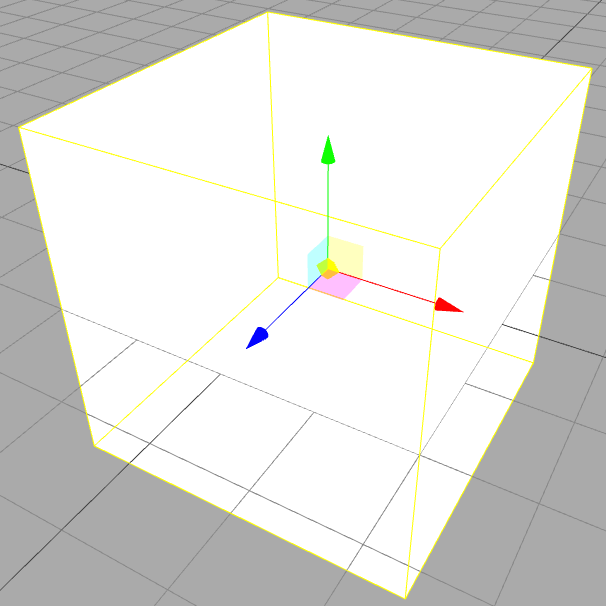
Shows translate gizmos along the x, y and z axis als well as gizmos that translate the cube along the xy, xz, yz and frustum plane.
In X3D gizmos can be realized with on of X3DDragSensorNode's decedents.
- SphereSensor
- SphereSensor converts pointing device motion into a spherical rotation around the origin of the local coordinate system. xd3om1
- CylinderSensor
- The CylinderSensor node converts pointer motion (for example, from a mouse) into rotation values, using an invisible cylinder of infinite height, aligned with local Y-axis. x3dom2
- PlaneSensor
- PlaneSensor converts pointing device motion into 2D translation, parallel to the local Z=0 plane. Hint: You can constrain translation output to one axis by setting the respective minPosition and maxPosition members to equal values for that axis. x3dom3
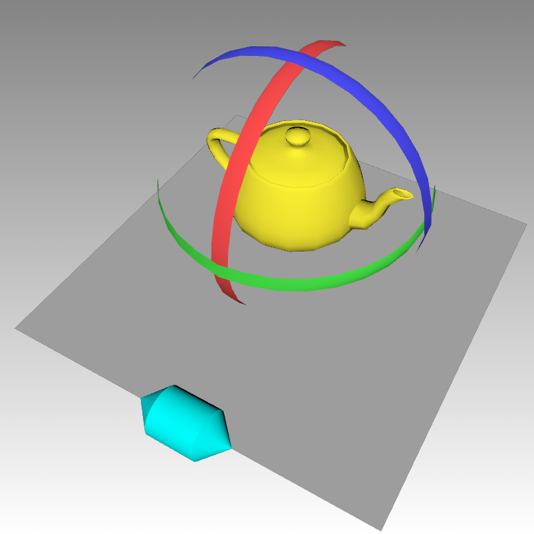
The sensors track drag events on their siblings. In the example above (which is taken directly from the x3dom website) the PlaneSensor tracks drag events on the cones and the cylinder that make up the cyan handle.
<group>
  <planeSensor autoOffset='true' axisRotation='1 0 0 -1.57' minPosition='-6 0' maxPosition='6 0' onoutputchange='processTranslationGizmoEvent(event)'>
  </planeSensor>

  <transform id='translationHandleTransform'>
    <transform translation='0 -5.5 8' rotation='0 1 0 1.57'>
      <transform translation='0 0 1.5' rotation='1 0 0 1.57'>
        <shape DEF='CONE_CAP'>
          <appearance DEF='CYAN_MAT'><material diffuseColor='0 1 1'></material></appearance>
          <cone height='1'></cone>
        </shape>
      </transform>
      <transform rotation='1 0 0 -1.57'>
        <shape>
          <appearance USE='CYAN_MAT'></appearance>
          <cylinder></cylinder>
        </shape>
      </transform>
      <transform translation='0 0 -1.5' rotation='1 0 0 -1.57'>
        <shape USE='CONE_CAP'></shape>
      </transform>
    </transform>
  </transform>
</group>
Every time it detects a drag event it converts it into a 2D transformation and raises an onOutPutChange event.
The callback processTranslationGizmoEvent is registered as an event handler.
In this function the position of the handle is adjusted to make it follow the drag movement, also the position of the teapot is adjust.
Having the the handles being 3d objects within the scene, that look touchable and intractable, make it easier for users find their way around the application. Instead of haven to learn keyboard shortcuts the user simply uses their intuition about how she would interact with objects in the real world.
Component Editor
- release 12th of june 2015
- thus after the work on SceGraToo started
- developed over a year
- developed by 3 people working part time
- cannot save or load x3d files
- serealizes the scene into a JSON format
{
  "0": {
    "type": "Box",
    "transform": "1.000000, 0.000000, 0.000000, 0.000000, \n0.000000, 1.000000, 0.000000, 0.000000, \n0.000000, 0.000000, 1.000000, 0.000000, \n0.000000, 0.000000, 0.000000, 1.000000",
    "referencePoints": ["p1", "p2", "p3", "p4", "p5", "p6"],
    "parameters": {
      "Size": [1, 1, 1],
      "Positive Element": "true"
    }
  }
}
- this would loose meta information like the IDs in comments.
Real-Time Collaborative Scientific WebGL Visualization with Web Sockets acm
Using web sockets instead of AJAX is an interesting approach. Especially the cut down on latency. It is over all very similar to the approach I was thinking about. Except that they propagate only some information, like the camera position and view angle. In SceGraToo's case the whole scene needs to be synchronized. So to have specttors like they have we either have to send the whoe model to the server after eacht change or use some kind of tree diff algorithm. They visualize a specific dataset in a specific format (which?). We only need to visualize X3D data, so there is no reason to use some generic Visualization tool kit, x3dom does a pretty good job doint this. on the other hand we not only have to visualize the data, but also manipulate it and this is way easiear in a descriptive scene graph instead of manimpulatiing webgl scenes or data formats like vtk.
ParaViewWeb pvweb
Simple to use out of the box, but needs a paraview server instance and paraview does not support x3d as an input format. So using this is sadly not possible unless an import filter is written. The visualization is mainly meant to explore data sets. There is no easy way to manipulate the input data. This can only happen by extending the visualization pipeline via python scripts on the server.